Table of Contents
Power
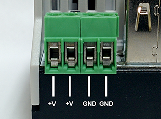
Four pin connector screw down connector, two parallel inputs for +24VDC and two parallel inputs for ground. Its only necessary to connect a single ground and single +24VDC input.
USB
There is both a USB A host connector and USB B device connector. There is only a single USB module on the microcontroller which implies that only one of the two USB connectors can be used at any given time.
Ethernet
The Ethernet connector provide a 10/100 Mbps auto negotiating internet connection.
Kard: Communication Slot (KardCom)
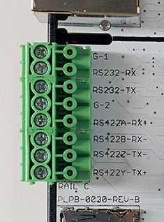
Communications Rail
Kard: I/O Slots (KardIO)
Each KardIO slot has four high current connections to an external rail, +VIN, +5VDC, +3.3VDC, 6 GPIO processor pins, shared I2C, SPI and UART pins.
I/O Rails (A/B)
There are two rails (A and B). Each rail has 12 I/O pins that go to 3 KardIO slots (4 each) and two rail power supply connections (+VRAIL and -VRAIL). The power supply connections allow for isolated I/O and independent voltages from the Quick™ power supply and on the A and B rails.
loading...
H-Bus Rail
The H-Bus is a 18 pin (2×9) 0.1“ center header that connects to a bus that sits in the DIN rail that allows other H-Bus enabled devices to communicate with each other with simplified wiring. Only 9 of the 18 pins are utilized by the Quick™ mother board. (+VIN, +5V, GND and 6 pins that go to the KardCom )
Jumpers
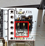
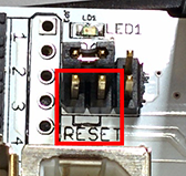
The jumpers allow you to reset your board/program. It also allows you to reset your board to the bootloader so that you can load a new program.
To reset board:
Short the two pins highlighted in red. (Note the position of the jumper.)
(This is equivalent to pressing the reset button on the Arduino Uno™.)
To reset board to bootloader (to load a new program):
Short the two pins highlighted in red. (Note the position of the jumper.)


